Traffic Engineering Extensions ==> for RSVP TE
Opaque LSA, Area-Local Scope (Type 10)
- Scope에 따라 3가지 타입의 Opaque LSA가 있고, TE를 위해 Area flooding Scope의 Type 10을 사용한다.
- 새로운 LSA가 정의됨 ==> MPLS Traffic Engineering LSA
MPLS Traffic Engineering LSA
Routers, Point-to-Point Links, Connections to MultiAccess Networks를 나타낼 수 있다.
(Multi-Access Links를 위한 LSA는 Network LSA로 충분해서 추가 정의가 필요치 않음)
Opaque LSA 는 Extended Link State Database를 구성하는데 사용
- extended link attributes를 모니터링
- 로컬의 제약조건을 기반으로 source routing
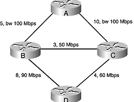
예를 들어 현재 사용가능한 10Mbps 이상의 대역폭이 보장되는 링크를 사용해서 라우팅을 한다.
- global traffic engineering
[참고] Router LSA 를 통해서 Regular Link State Database를 구성한다.
This LSA performs essentially the same function as Router (type 1) LSAs: It identifies the originating router, the router's neighbors, and characteristicsin particular the TE parametersof the links to those neighbors. Because the necessary TE parameters are carried in this LSA for interfaces to both point-to-point and multi-access links, there is no need or a special "TE version" of Network (type 2) LSAs. The existing type 2 LSAs are sufficient for the CSPF calculations.
The Opaque Type of the TE LSA, as shown in above, is 1.
Instance differentiates this LSA from other TE LSAs. Because this field is 24 bits (unlike a regular LSA ID field, the Opaque type takes up the first 8 bits) there can be a maximum of 216 = 16,777,216 TE LSAs in a given traffic engineering area.
Recall from Section 10.1.2 that this field in the general Opaque LSA format is called the Opaque Type field and is defined as an identifier specific to the LSA application.
The payload portion of the TE LSA is one or more TLVs of one of the following types:
Router Address TLV (TLV type 1) carries in its value field an always-reachable IPv4 loopback address of the originating router. This address is normally also the RID of the originator, but of more importance here is that the address serves as the endpoint of any LSP egressing the originator.
Link TLV (TLV type 2) describes the TE parameters of a single link. The value of this TLV is a set of sub-TLVs. The format of a sub-TLV is the same as any other TLV; it is a sub-TLV only by virtue of the fact that it is in the value field of another TLV.
The sub-TLVs of the Link TLV, and their types, are as follows:
Link Type (type 1) carries as its value a 1-byte field that specifies the type of link being described: point to point (link type 1) or multi-access (link type 2).
Link ID (type 2) serves the same purpose, and uses the same semantics, as the Link ID in Router LSAs: It identifies the LSR at the other end of the link. If the link type is 1 (point-to-point link), the link ID is the RID of the neighbor. If the link type is 2 (multi-access), the Link ID is the interface address of the DR.
Local Interface IP Address (type 3) specifies the IP address of the originator's interface to the link. This sub-TLV can carry multiple IP addresses if the interface has more than one address.
Remote Interface IP Address (type 4) specifies the IP address or IP addresses of the neighbor's interface to the link, if the link is point to point. If the link is multiaccess, the value of this sub-TLV is 0.0.0.0 or, alternatively, the sub-TLV is not included at all.
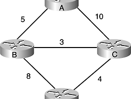
Traffic Engineering Metric (type 5) carries a 4-byte TE metric
Maximum Bandwidth (type 6) carries the maximum bandwidth. This is a 4-byte value specifying the bandwidth in bytes (not bits) per second.
Maximum Reservable Bandwidth (type 7) carries the maximum reservable bandwidth. This is also a 4-byte value specifying the bandwidth in bytes per second.
Unreserved Bandwidth (type 8) carries the unreserved bandwidth for each of the eight setup priority levels 0 through 7. they are listed in the sub-TLV in order from 0 to 7. Because each bandwidth size is described by a 4-byte number (again in bytes per second), the total length of the value field of this sub-TLV is 32 bytes.
Administrative Group (type 9) specifies the administrative group (link color) or groups to which the link is assigned. The value is a 32-bit field, with each of the bits representing one of 32 possible administrative groups. If a bit is set, the link belongs to the group corresponding to that bit position. The most significant bit corresponds to administrative group 31, and the least significant bit to group 0. In above figure, the value of that link's affinity bit (yet another name for administrative group) is 0x3, so the link belongs to administrative groups 1 and 0 (and hence to whatever "colors" the network administrator has associated with those two numbers). In above figure, this same TLV value is labeled as "color," and the value of 0 indicates that the links in the database do not belong to any administrative groups.
Every Link TLV must have a Link Type and Link ID sub-TLV, but the other sub-TLVs might or might not appear in the Link TLV depending on whether the TE parameter is specified.
A significant point is that type 10 Opaque LSAs, on which the TE LSAs are built, have area flooding scope. That means that when you design a TE domain using OSPF, its boundaries must correspond to the boundaries of an OSPF area. Typically, because a TE domain is in the core of a network, the domain boundary corresponds to OSPF area 0.
And because the TE LSAs flood throughout the area they are originated in, all routers in the area, whether they individually participate in TE or not, must recognize and flood these LSAs.
[Packet Example]
<MPLS TE LSA with Router Address TLV>
<MPLS TE LSA with Link TLV>
[참고]
RFC 3630 - Traffic Engineering (TE) Extensions to OSPF Version 2
'IT Tech > Network' 카테고리의 다른 글
| [네크워크] MPLS TE SRLG(Sharead Risk Link Group) (0) | 2011.06.10 |
|---|---|
| [네트워크] MPLS Tunnel Reoptimization (0) | 2011.06.08 |
| [네트워크] MPLS Implicit / Explicit NULL labels (0) | 2011.06.07 |
| [네트워크] CSPF (Constrained Shortest Path First) 동작원리 (0) | 2011.06.03 |
| [네트워크] OSPF의 SPF(Shortest Path First) 일반적인 동작 원리 (0) | 2011.06.02 |
| [네트워크] OSPF Router LSA Packet Format (0) | 2011.06.01 |
| [네트워크] OSPF DB Description 패킷 구조 (0) | 2011.05.31 |
| [네트워크] OSPF Opaque LSA (0) | 2011.05.31 |
| [네트워크] VLAN Trunk 간단 개념 (0) | 2011.05.10 |
| [네트워크] IGMP SNOOPING (0) | 2011.05.10 |


